Intro to Fabrication: Week 5

Assignment

This week’s assignment: fabricate something using primarily two different materials. The materials cannot be acrylic or plywood.

In all of my fabrication projects, I’ve been drawn to using more natural material sources – wood, wool felt, capiz shells, glass. This week, I wanted to incorporate rattan, particularly the cane webbing and sunburst weave pattern known as “solihiya” in the Philippines. Rattan is an everyday material in the Philippines, and its usage is very iconic in furniture pieces.

While I was repotting some plants over the weekend, there were a few pots I thought about elevating off the ground – but didn’t have any plant stands to set them on. Inspired to meet this need and to continue along my housewares theme, I decided to go for making a plant stand with rattan and wood.

Materials

I’ve been curious about using other kinds of wood, so I went back to Dyke’s Lumber and picked up a few feet of a 2x4 of mahogany. I chose mahogany because I love its reddish-brown tone and wanted to make a reference to "Philippine Mahogany" (while it’s not true mahogany, it’s a term for species of wood native to southeast Asia).

Picking up mahogany from Dyke’s Lumber in Brooklyn.

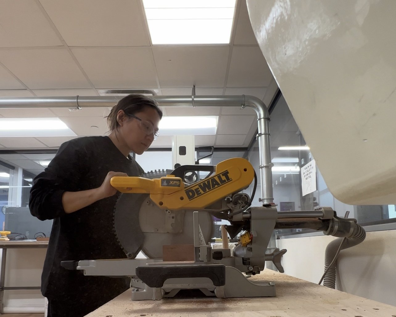
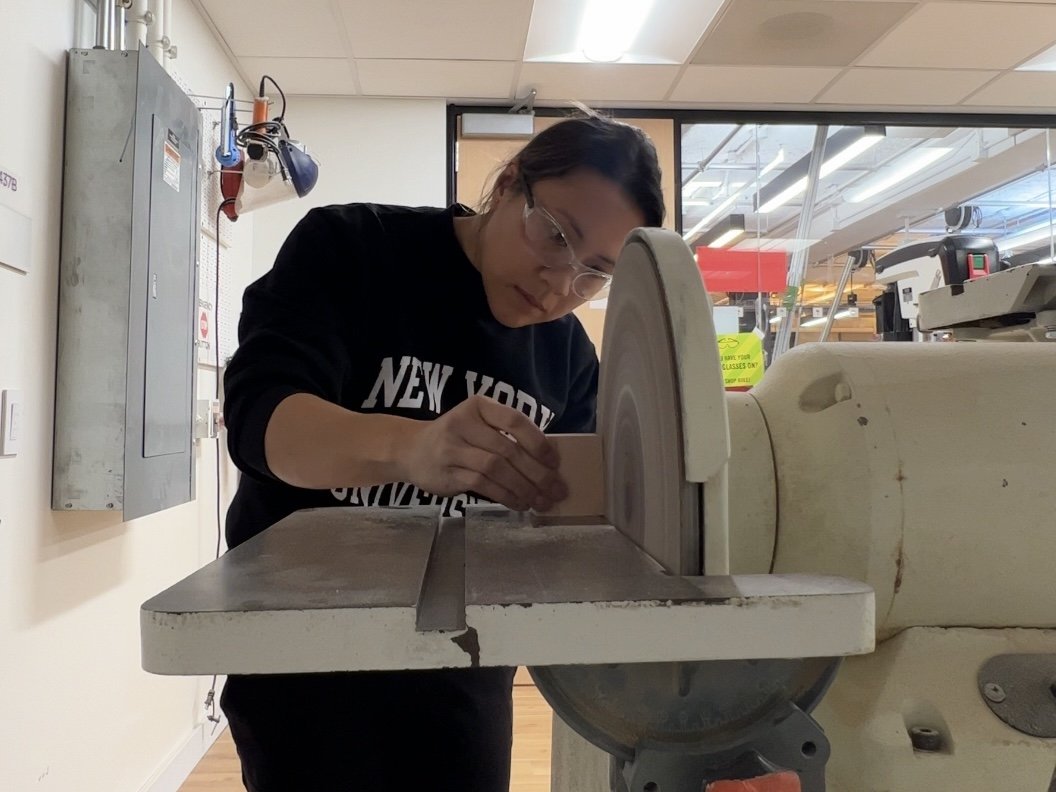
Using a miter saw to cut the 2x4.

Process

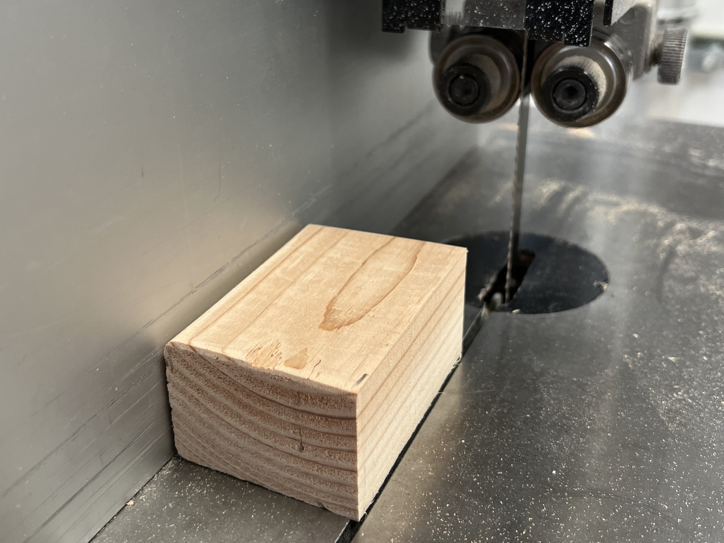
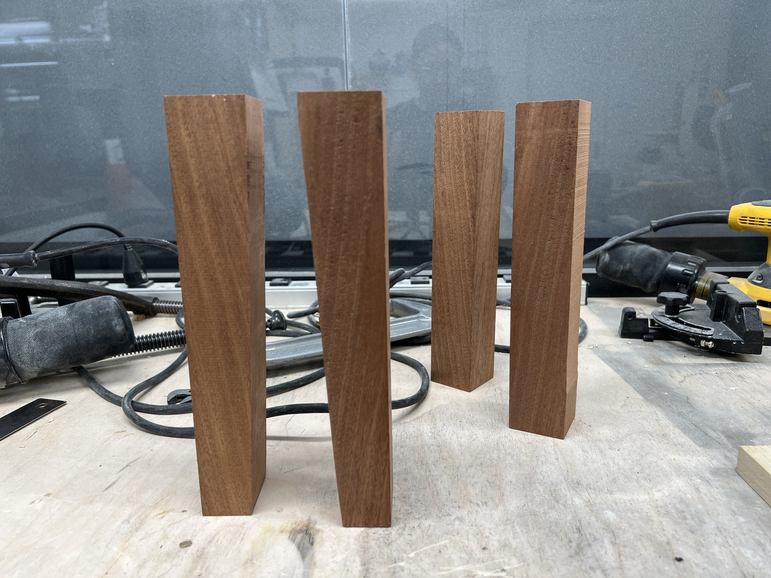
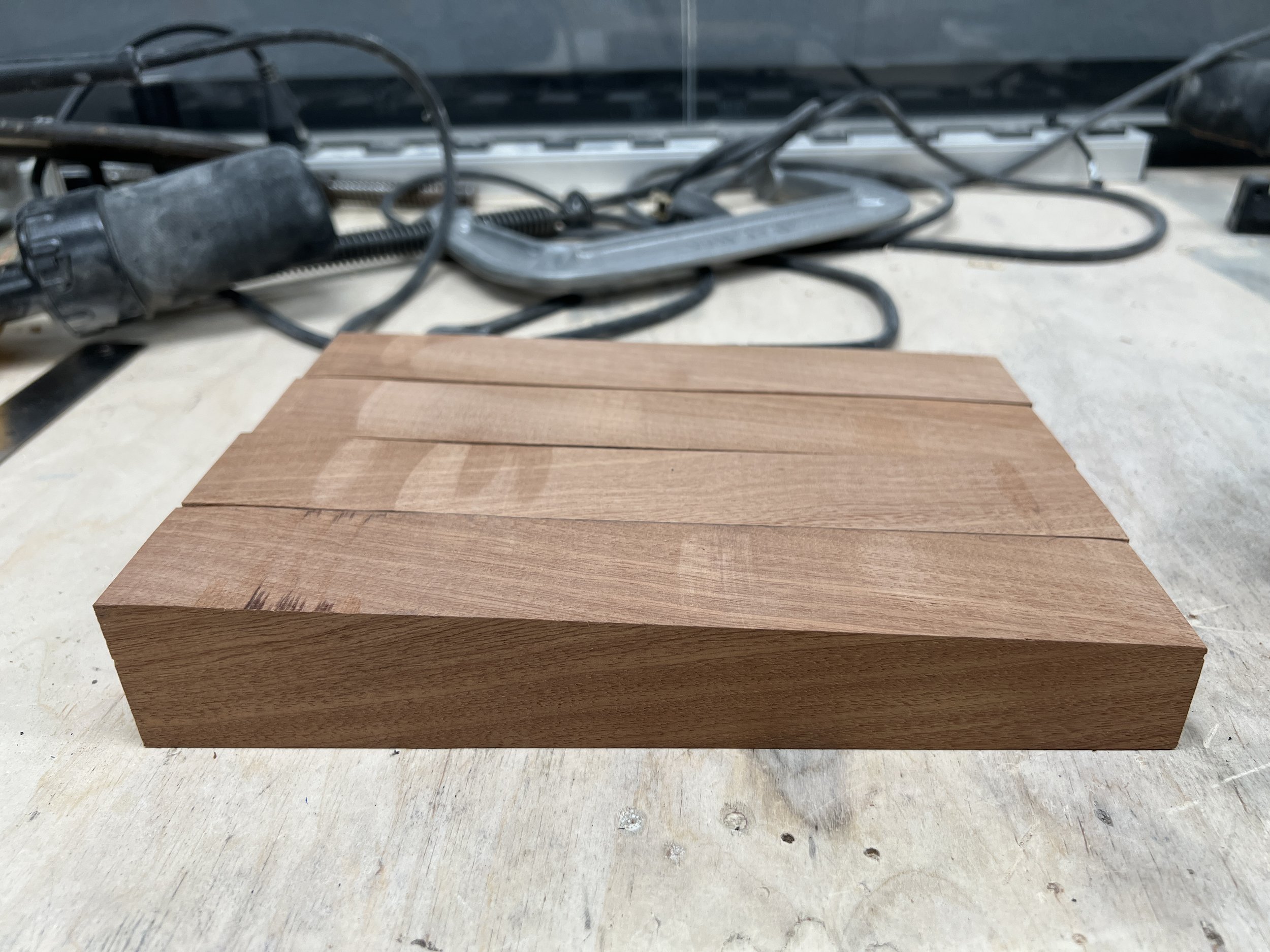
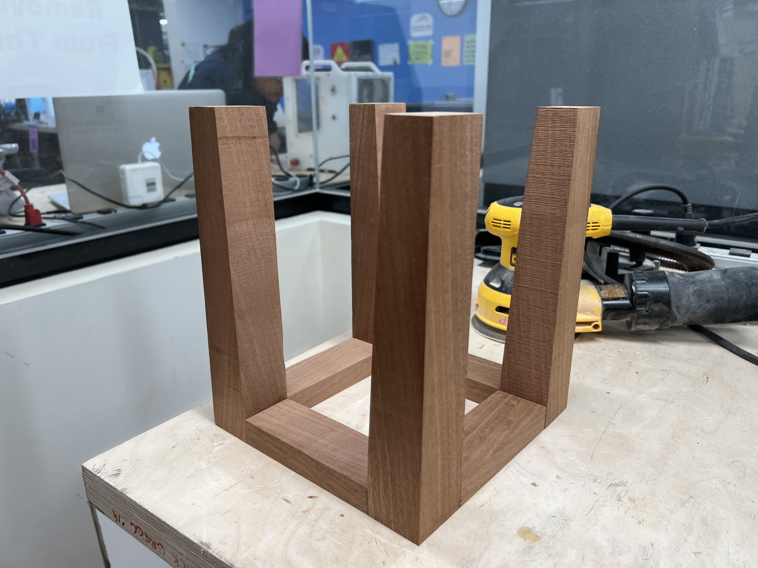
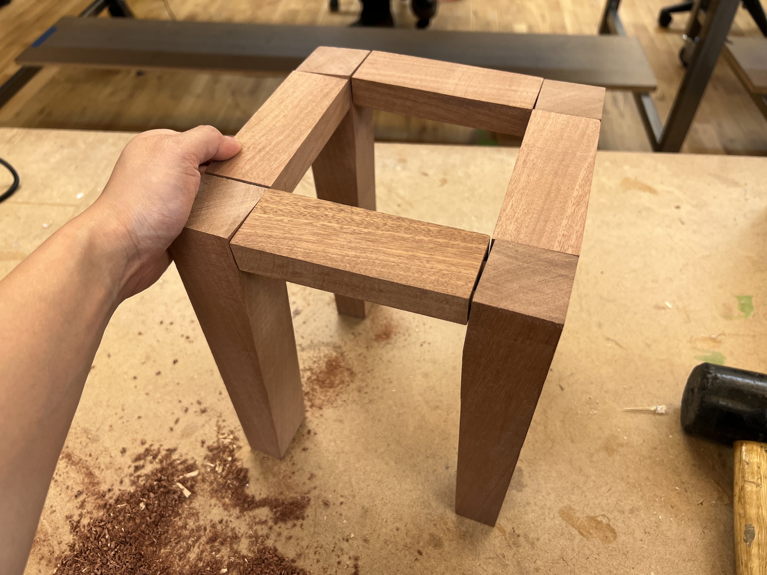
I felt pretty satisfied with my miter saw cuts and band saw work. I cut the 2x4 into two 10-inch pieces, and split those in half with the band saw to make the legs. I wanted to create tapered (slightly angled) legs, but didn’t have a solid jig, so I just freehanded the angle cut. I lined up the legs in a row to see if they were about the same. They weren’t perfect, but overall, not bad. After that, I cut another 5-inch 2x4 piece, which I quartered to create the top frame. I placed all of the pieces together to see if they would fit.

Fasteners

I struggled with the fasteners portion of this project. I picked up dowel pins at the lumber store, and thought this would be how I could attach the pieces without having any visible screws. I found the right drill bit size, attached it to the drill press, made a few holes – but quickly realized how difficult it was to properly align the holes and pins so that all of the edges were flush and the dowels fit tightly.

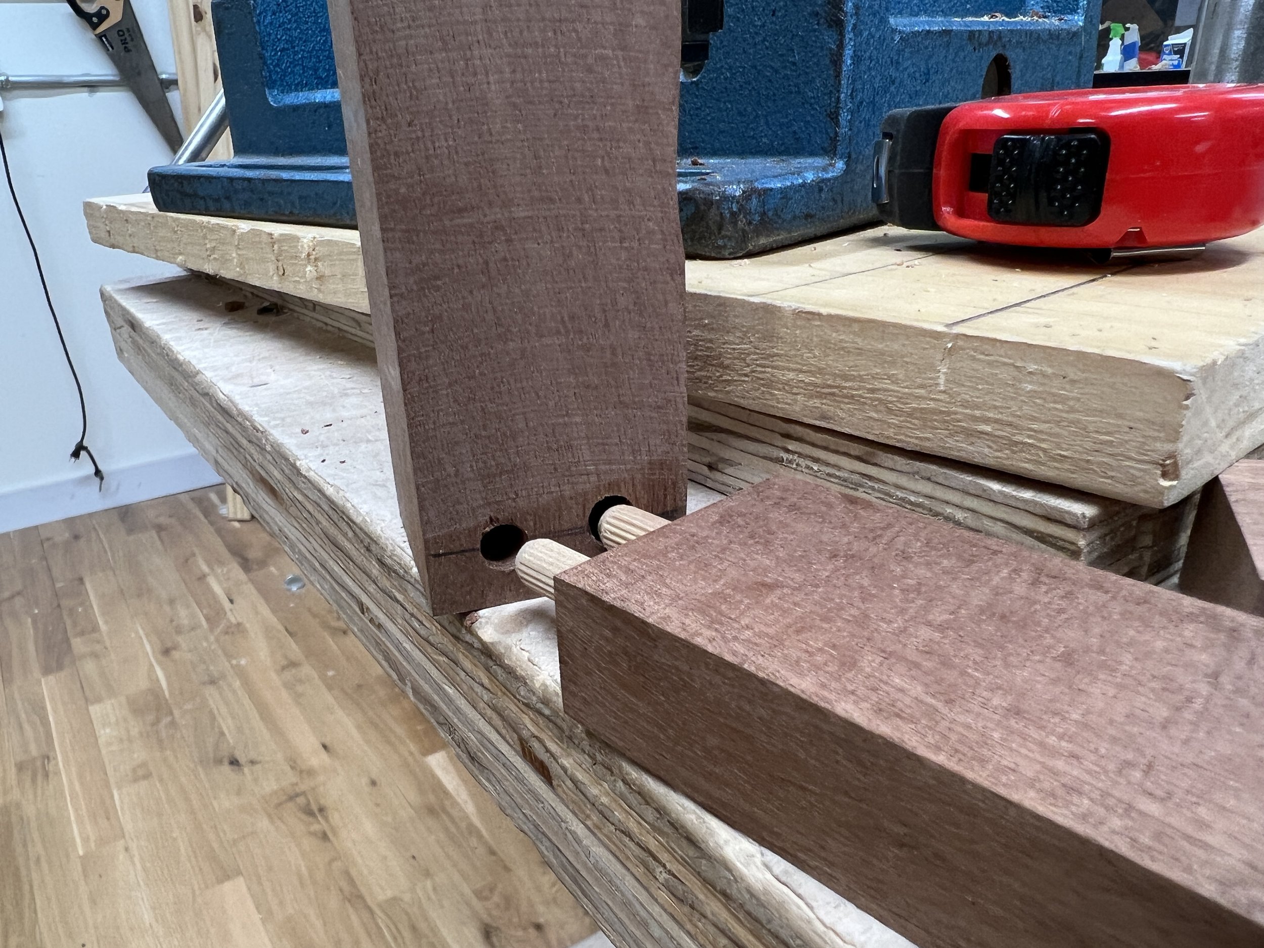
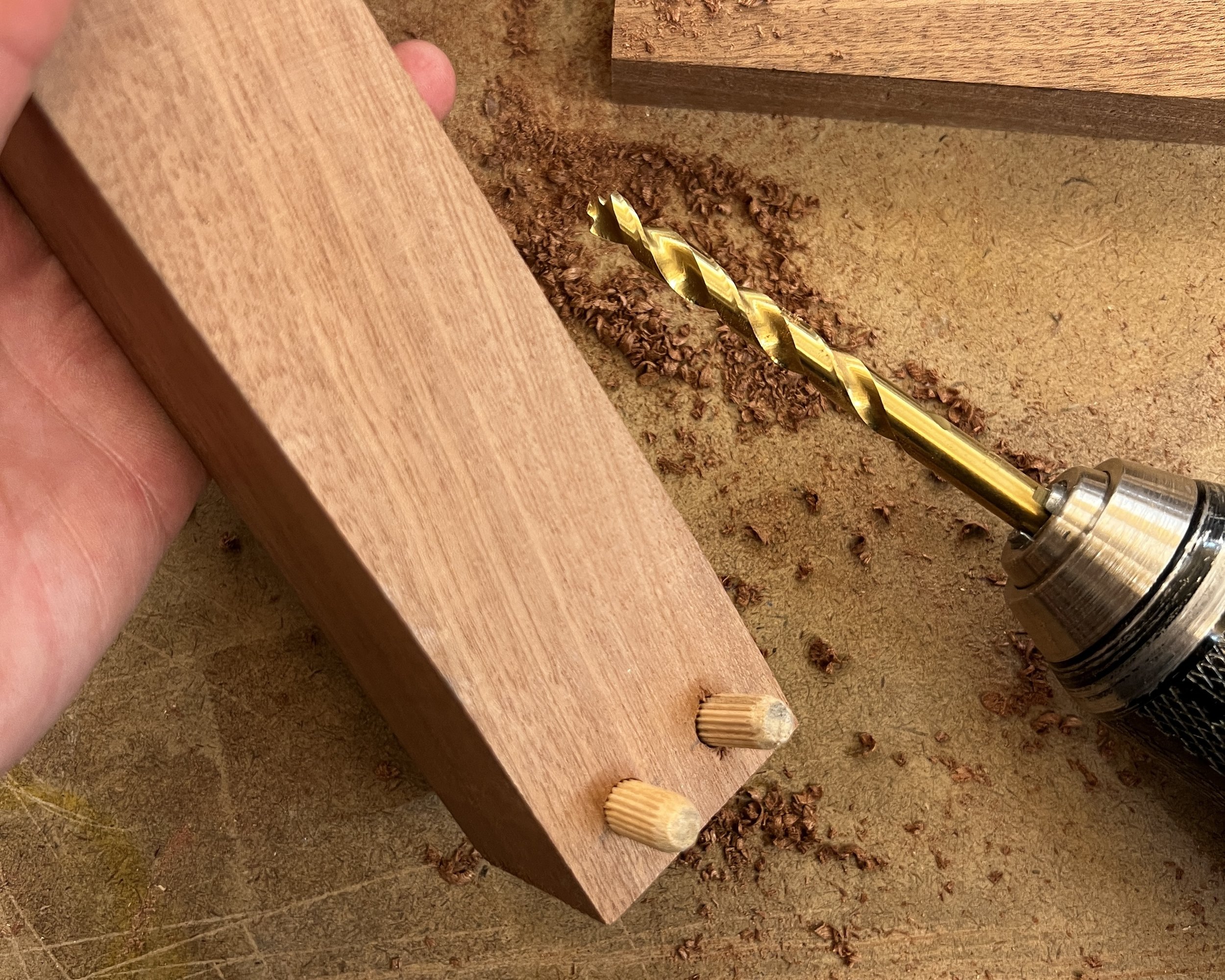
After the first two pins, I was a bit frustrated from this project being much harder than it seemed and looked, and I abandoned using the drill press to create the dowel pin holes. Still wanting to conceal my fasteners, I thought about making the pocket screws we reviewed in class. But even with the assistance of shop staff, I couldn’t find the pocket hole jig. So I decided to try again with the dowel pins, this time using the hand drill.

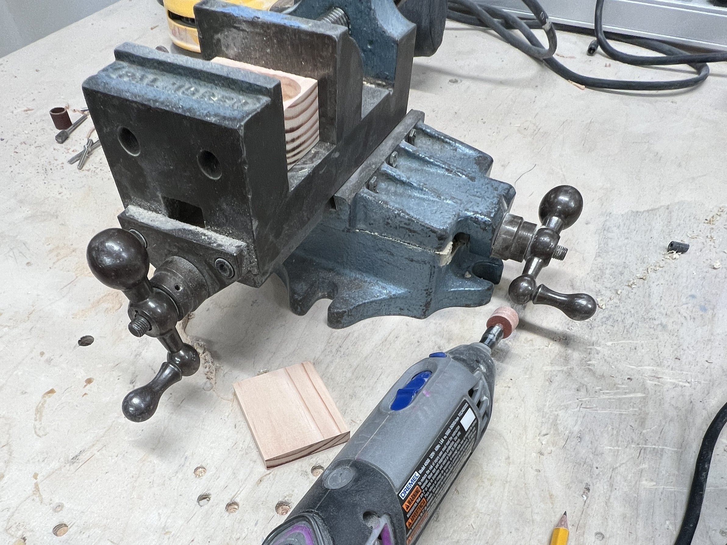
While I got most of the pieces attached together, it just still wasn’t quite right and I wasn’t happy with how it looked. It would still need wood glue to stay secure, and the pieces of wood weren’t lining up properly – which really bothered me. I decided to scrap the dowels altogether and resorted to gluing all of the joints together instead. I haven’t done any wood gluing with clamps yet, so this was a good exercise in technique and patience. I experimented with making my own wood filler with my pile of sawdust to close up the small gaps between the joints.

Result

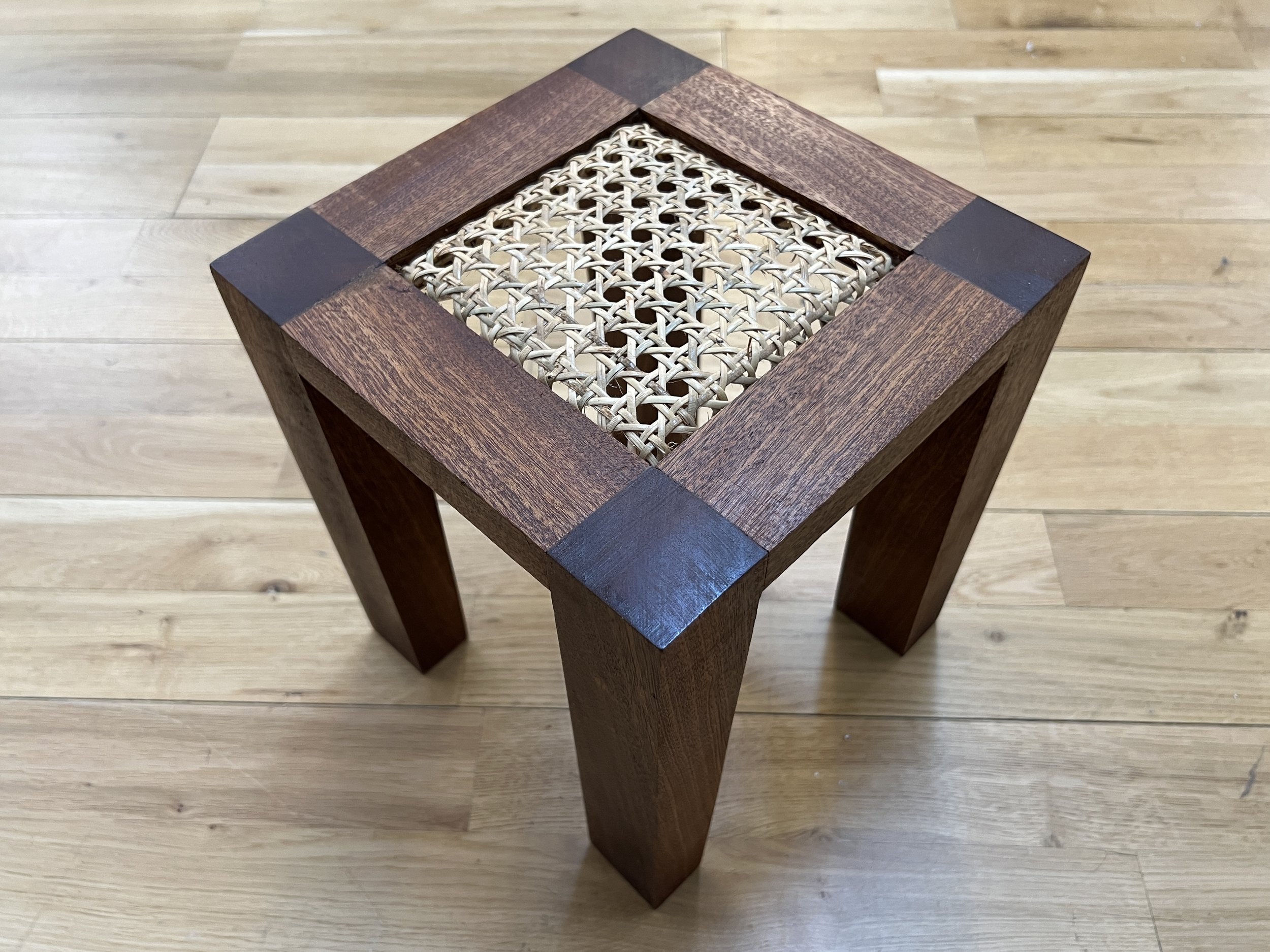
The plant stand (or perhaps a stool or side table?) ended up feeling like a fairly solid piece after the glue dried. The next step was to add my rattan cane webbing as my second material. I cut a piece that would the square opening and soaked it in lukewarm water for about an hour to soften the rattan and make it pliable. As I fit the piece into the frame, I used a staple gun to fasten the rattan to the wood.

Fitting the rattan cane webbing into the wooden frame.

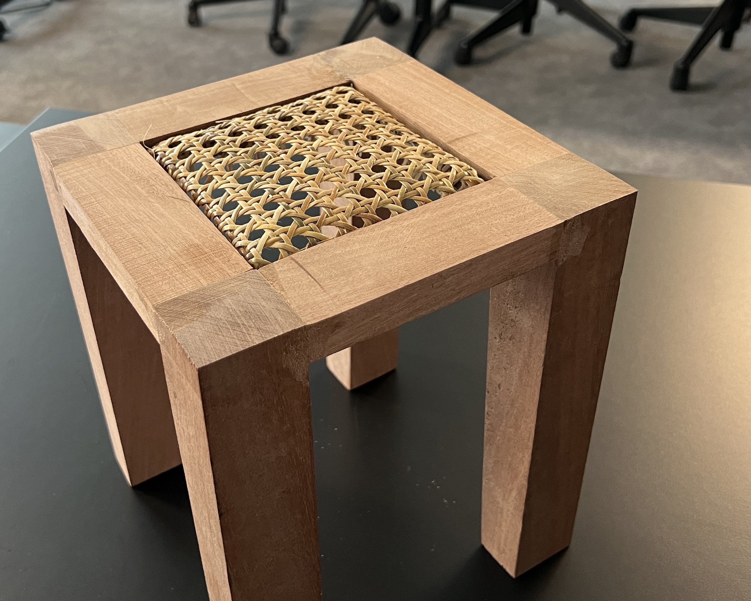
The plant stand as presented in class.

After showing the almost finished piece in class, I went back to the shop for the last bit of sanding and finishing. I smoothed out some uneven parts and worked my way through the sandpaper grits, up to 400. I used a utility knife blade to scrape off the excess dried glue. Finally, I wiped on linseed oil, which turned the wood into a dark and rich mahogany color. I’ll probably take some reed spline to fill in the edges as the final touch. Overall, I’m very satisfied with this piece, even with its imperfections and the moments of failure that I experienced while making this. I would definitely look into creating a template for myself to produce more of these more efficiently.

Intro to Fabrication: Week 4

Assignment

This week’s assignment: create an enclosure surrounding something. I made a lamp – an enclosure surrounding a light bulb.

Thinking about my Philippine heritage theme for fabrication, I was inspired by Filipino parols, which are star lanterns commonly displayed throughout the Philippines during the Christmas season, and capiz shells, used to make parols but are also often part of windows, doors, and other decorative products. I’ve also been following a secondary theme of making housewares, so I felt that making a lamp would fit right into my object family.

Materials and Process

I knew I wanted to utilize an exposed light bulb and a pack of square-cut capiz shells. I ordered a wiring kit for the bulb socket and utilized another part of the remaining poplar wood I have in the shop. I started out by making a square base from the 2x4 piece, but later, I cut the corners at an angle to create an octagon shape. I made sure to test out different bit sizes with the drill press to ensure that I had a good fit for the black plastic socket shell pieces – even making sure that I cut into the wood at different levels for the change in widths.

However, I didn’t realize I was fitting the shell into the base upside down until I started wiring the socket. This definitely served me a lesson in order of operations. I should've tried to assemble the wiring kit together before making the very thing that would enclose it.

From left to right: square capiz shells, a lamp wiring kit, and a vintage style LED bulb.

Testing out the size of the drill bit with the plastic bulb socket shell.

A photo of the lamp base with the bulb socket inserted as I thought it would fit – before I started wiring it and realized I had it upside down.

A close-up of the square-cut capiz shells to see their translucent texture.

Result

To my relief, the light bulb and switch itself all worked fine. However, the way I ended up positioning the bulb socket in the base meant that instead of the pieces fitting perfectly flush inside, it all stuck out. The light bulb wasn’t sitting securely in the opening. It was at this point that I began sketching out how I could attempt to make this base again. The lamp works and is fine for now, but there are some modifications and next steps that I want to get to:

  1. Fabricate a new base that will house the entire bulb socket. This may require gluing two pieces of wood together.

  2. Laser cut the capiz shells into small subway tiles and apply them to the base as a finish.

  3. Change the rotary switch or add a dimmer to reduce the bulb’s brightness. (I also need to figure out how to restore the glass after getting a few scratches and too many of my fingerprints.)

Going back to the drawing board. When I realized the correct orientation for the socket, I tried to get a grasp of how I would have to drill the wood on my next attempt so that the light bulb could sit flush inside the base.

Let there be light – for now! My current lamp as is.

Intro to Fabrication: Week 3

Assignment

This week’s assignment: laser cut two of the same thing:

  1. One must be small

  2. One must be big (1 ft. x 1 ft.)

Materials

I’ve already laser cut acrylic, wood, and cardboard for previous projects, so I wanted to try using a new material. Inspired by thick felt trivets I’ve seen online, I wanted to experiment with making my own. I purchased a piece of 5mm thick merino wool felt from a shop on Etsy and figured I could cut a coaster as my smaller piece, and a trivet as my larger piece.

As for the design of the vector cut itself, I thought of this project as a chance to prototype and make my own interpretation of an idea my mom has shared with me – making a trivet in the shape of the Philippines. What I envisioned: create a whole set of trivets in the shape of individual islands of the Philippines that could be the base for a whole spread of dishes on a table. (And if I were to take this idea even further, I’d put a regional dish on that island’s trivet.)

Process

For this assignment, I chose to work with the shape of Leyte, the island in the Visayas region of the Philippines where my maternal grandparents are from. I tested out the scale of the island as a trivet and coaster with cardboard, and from there, moved on to attempting the cut on the wool felt. It was tougher than I thought. I had to do multiple passes with the laser cutter, and most of the thick felt still wasn’t cut all the way through. The edges were also darkening and the felt was developing a burnt hair scent. I ended up having to cut parts of the outline with a utility knife and cleaned up some portions with scissors.

The cardboard pieces I laser cut to test out the size.

Cutting the wool felt with the laser.

Result

I would really love to nail the settings for the wool. I still have some wool left over to experiment and figure out the right power and speed settings that ideally would not burn the felt. The other thing I need to resolve about these pieces is the smell. I might try putting these in the freezer to remove the odor.

The final wool coaster and trivet with a cup of tea and empty bowl for scale.

Intro to Fabrication: Week 2

Assignment

For our second assignment, we were tasked to make two of the same thing using two or more methods of fabrication (no laser, no 3D printing) with tools that we covered: band saw, miter saw, panel saw, disc/belt sander, and drill press.

I picked up a 2x4 of poplar from the lumber shop for this week’s project. Working with my theme of Philippine heritage, I pursued making five rice paddles – an essential kitchen utensil for scooping cooked rice.

Drawings

Designing a simple kitchen utensil is actually more difficult than you think it might be. I thought about how the rice paddle would function when sticking it into a pot of rice, or how it would fit in my hand. I started sketching out a few shapes before moving on to paper cutouts to get a feel for what size and shape to go with. I also asked a few friends and family for their opinion.

Process

I watched a few tutorials on YouTube to learn a few different woodworking approaches to making wooden spoons and spatulas. I saw a technique where one person used the band saw to cut the flat outline, tape it all back together, and then turn the block of wood sideways to cut out the shape of the profile. I went with this method to create the rough shape of the paddles.

The rough shape of the paddles after being cut with the band saw.

One issue though: I should have cut the profile of the paddle on the scooping side much thinner. I ended up spending a lot of time on the sanding machine trying to subtract more material from each one. I also struggled with shaping the inner curve of the paddle. I used the top rounded end of the belt sander to achieve the final shape, and then cleaned up the shape and surface further with hand sanding. I used a power hand sander in addition to using a wooden dowel (to get the rounded inside corners of the handles) and a rectangular scrap piece of wood as sanding blocks.

A rice paddle all done with power sanding and ready for finer hand sanding.

Result

As you can see, the five paddles are close enough, but not exactly the same. Even when I thought I was cutting and sanding each piece evenly, there were variations in size and shape. I added a finish of mineral oil to protect the wood and prepare them for actual rice cooker usage. The oil gave the paddles a slightly darker color.

Five rice paddles – that you can also stand up on the kitchen counter when not in use.

Big LEDs: Week 1

Assignment

Research a lighting project, event, object, or sculpture that interests you. Write a short blog post describing it both technically and artistically. Try to describe it using the properties and goals of stage lighting

Lighting Project

For this assignment, the project I chose was "Flylight” by Studio Drift, an interactive site-specific art installation that mimics the behavior of a flock of birds in flight. I’ve seen some of Studio Drift’s work at the Shed and have been fascinated by the way they use light and movement in their installations.

“Flylight” is composed of eighty glass tubes that light up in response to the movement of the viewer. In relation to the Four Goals and Properties of Stage Lighting: The composition of this site-specific work is important: the way that the lights suspend from the ceiling and high above the viewers give it the impression of the lights as a flock of birds. The shape of the light bulbs themselves provide a revelation of form. The patterns in which the light moves (different bulbs lighting up in various patterns to mimic birds in flight) create the mood.

Intro to Fabrication: Week 1

Theme

Over the years and especially from my most recent visits to the Philippines, it has become a part of my personal mission to honor and preserve my Filipino cultural heritage in America. I've become passionate about highlighting Philippine coffee and handweaving traditions in other projects outside of NYU, and it's a theme I'm contemplating on building upon for my thesis. In the realm of learning fabrication, I believe there are so many cultural references and design motifs in the Philippines to take inspiration from, so I plan on building a family of objects that relate to this theme of heritage.

Assignment

For our first assignment, we were specifically required to make a box with the fabrication methods we learned in class: utilizing the band saw, drill press, and belt sander. The top/lid of the box should be attached with a screw and swiveled to open.

I knew immediately what kind of box I wanted to make that would fit my theme. I chose to make a miniature version of a “balikbayan box” – the large cardboard boxes full of items that Filipinos overseas or in America would send to their families back in the Philippines (the term “balikbayan” refers to a Filipino returning to the Philippines after being away/abroad).

Drawings

Some rough sketches of what I envisioned the box would be and how the box turned out (overall, quite similar).

Process

I found the whole process overall very therapeutic. It was nice to switch it up from digital work and create something physical, spend time away from my screens, and truly focus on only one task at a time. Sanding wood down to a smooth surface was just incredibly satisfying. I quickly learned that fabrication is a whole lot of learning by doing when it came to how much pressure to apply to the wood against the belt sander, how to adjust components on different pieces of machinery, making use of the dremel to smooth out the inside of the box. This all also came with a splinter that I’ll have to learn how to properly take out.

Result

I didn’t think about what the contents of this balikbayan box would be until after I made it. It would make the most sense to fill it with objects that are commonly sent in these boxes: clothes, shoes, personal care items, magazines, canned goods, etc. A friend suggested making a box that was big enough to perfectly fit just one can of Spam – but the scrap piece of wood I had could not make that happen. I remembered I had a miniature tube of Colgate toothpaste (note: since there’s no direct translation of “toothpaste” in the Philippines, Filipinos often refer to any tube of toothpaste as “Colgate”) that came in the airplane kit from my most recent Philippine Airlines flight to Manila. It fit inside perfectly. I would consider making this box again but in larger sizes to function as a trinket box.

Week 6: Final Project

Background

Our assignment for the final lens was to create a lens using any modality (or combination of modalities) intended for one of the following applications: Utility/Tools, Games, Education, Commerce (Advertising, Fashion, Shopping/Retail, etc.), Storytelling, or Artistic Expression.

When I started to work on this lens, I was inspired by recently having to dress up in “Hogwarts in Manhattan” theme for an in-house competition at my gym. I was a big Harry Potter nerd growing up, so I had no problem digging out my old Gryffindor robe and Harry Potter glasses, even though I’m technically a Ravenclaw.

However, because I chose to work in the world of Harry Potter, one of my first concerns in building a lens was taking into consideration what already has been done in Snap and/or AR. Some previous applications in Snapchat included virtual Hogwart house outfits for Warner Bros' new Tournament of Houses series, Quidditch-themed Bitmoji, and a shoppable mini Hogwarts Mystery game where you could practice spells by drawing on your screen.

The Quidditch-themed Bitmoji lens in Snapchat released on July 31, 2018.

A big draw of augmented reality for me is being able to converge the worlds of fantasy and reality. In the same way that you could cosplay characters, drink butterbeer (I even made it once myself), and get a wand at the Ollivanders in Universal Studios, it’s fun to have these elements of fantasy and magic in your “real” life.  

So as I approach this final project, I considered using the world/environment modality and applying this lens as part of an experience at a Harry Potter store or theme park.

Through the Lens (of a Seeker)

I created a lens based on the Golden Snitch (also just known as the Snitch), a small golden ball that would fly (and sometimes pause or hover) around the field in a game of Quidditch. A team’s Seeker has to catch the snitch in order to end the match. In Lens Studio, I worked on mimicking the Golden Snitch’s movement by using move and rotation tweening to animate the object. I also experimented with VFX including confetti particles that could possibly be triggered by “catching” the snitch.

A screenshot of the lens in progress in Lens Studio.

A demo of the Seeker lens in action. Since this test, I adjusted the movement of the snitch to “fly” a little further off the screen, but this video gives you a sense of the animation.

Additionally, I was thinking about more applications of this playful world lens in a real place where the user could make more magical discoveries. I added image tracking to a blank folded piece of parchment paper. By moving your lens over the paper (come back to this image after you load the lens in Snapchat), the Marauder's Map – a magical map of Hogwarts – would reveal itself.

GIF of the Marauder’s Map animation.

Next Steps

There are many more next steps and possibilities for this lens. It would be great to continue building this lens out with scripted interactions (getting close to the snitch or catching it), adding audio components and triggers, having a front camera face lens component, and mapping objects to custom landmarks (back to the idea of applying this lens to Harry Potter World).

Week 5: Environment

During Week 5, we explored the environment modality and created world lenses in Lens Studio. Our assignment for the week: create a lens that encourages users to go outside and interact with their environment in some way.

Winter in New York City has been unusually warm lately and with barely any snowfall. I truly enjoy seeing the city when it’s covered in a blanket of snow (and I’m known for venturing out in snowstorms to document photos and videos), so the weather this past season has been disappointing. This very disappointment inspired me to create a lens that would give you the sense of being in a snowy world.

I started by playing around with a snow texture for ground segmentation and mixing it up with snow particles and the ice post effect. While playing around with the snow texture, I accidentally covered up half of the screen so that the view appeared to be deep within the snow – but I actually liked the effect and decided to keep it. What would you do if you were buried in snow? That made me think of adding objects like a snowboard, but after presenting this concept, I realized that foot-tracking a snowboard that is usually sideways and strapped to your feet didn’t make the most sense. I decided to try out the foot tracking feature with snow shoes (more logical) instead.

A screenshot of the 3D scene with the default foot mesh inside the snowshoes.

Trying out foot tracking was a learning experience with understanding how to properly attach the objects to the foot mesh and occlude the feet – and I had some glitchy looking outcomes. Ultimately, I decided it was best to only track the snowshoes to your feet instead of making them appear like they’re on your feet (they just didn’t look right).

Occluded feet inside the snowshoes not looking that realistic.

The final scene in Lens Studio.

A demo of this “Snowed In” lens in action while walking outside.

Week 4: Body

Our assignment for Week 5: Create a lens that utilizes the moving body to trigger digital content.

A few weeks ago, a few friends and I talked about learning how to dance the chorus of NewJeans’ “OMG” (a major earworm, by the way) so that we could do the dance together at some point. Since then, I’ve been sent so many video memes about the dance or other people performing it, and just felt like I absolutely had to make a reactive body lens to this song for this assignment.

A video of NewJeans themselves rehearsing “OMG” – in case you may be inspired to practice it yourself.

I wanted to understand how body tracking and triggers worked in Lens Studio, so I opened up both the Full Body Triggers template and the Body Segmentation template and started going through the Inspector panel for the various objects and effects. The possibilities feel unlimited here.

Exploring the Full Body Tracking Controller and attached objects through the Full Body Triggers template.

Ultimately, I wanted to create a lens that could be synced to the audio of the chorus. I used the Timed Effect example in the Body Segmentation template and modified the controller script and effects to time the different scene objects to the music. I also added an “OMG” graphic that’s triggered by moving the hand above the head (with an invisible “button”), which should appear while doing the signature “OMG” dance move.

A screenshot of the Controller Script for cycling through each effect that I timed to the music.

A snippet of the “OMG” lens in action.

My own attempt at the dance for a quick lens demo.

Week 3: Image

Our assignment for Week 3: Tell a story across AR image targets. Pick a piece of print media (magazine, newspaper, book, something you’ve created). Choose at least 2 images within it (up to 4) and augment them to create a narrative.

I chose to work with the Approval Matrix printed in New York Magazine, which is their “guide to what’s highbrow, lowbrow, brilliant, and despicable.” Because everything selected is summarized down to a brief point, I often don’t always know the reference or the full picture (pun intended) of the point on the matrix. This is where I thought the Approval Matrix could benefit from some additional images (or text) through AR to add to the storytelling.

Original Approval Matrix Image

Below is New York Magazine’s Approval Matrix from the Week of February 13. It is published online and in the printed magazine. This image can be used for testing the lens.

Lens Studio AR

I chose three items in the Highbrow/Brilliant quadrant to work with: famous whip performer Jack Lepiarz (didn’t know who he was), LeBron James breaking the all-time scoring record in the NBA, and the Copland Dance Episodes at the New York City Ballet. I started with the Copland Dance Episodes by experimenting with overlaying a GIF I made from a video preview of the New York City Ballet performance over the original photograph, and for Jack Lepiarz, I found a TikTok clip of one of his performances.

Preview

For the LeBron James point on the Approval Matrix, I overlayed a clip of him making the all-time scoring record basket. I experienced some issues publishing this lens; I will update this page with the Snap lens link when it’s available.


Week 2: Face

Our second assignment: Pick an adjective and create a face lens to depict its meaning.

For this assignment, I picked “whimsical” as my adjective. Whimsical means “playfully quaint or fanciful, especially in an appealing and amusing way” and I decided to go for a filter that felt like being at a garden tea party, à la Alice in Wonderland. I was browsing the Asset Library and came across a 3D stack of plates, bowls, and cups in the Kitchen Pack and thought they could make a great little hat.

I also wanted to use this first exercise in Lens Studio to play with some of the face effects like Liquify (to enlarge the eyes and give them a bit of a cartoonish look), Retouch (to soften skin and whiten the eyes and teeth), and the Makeup Controller (to add blush, lipstick, and eyebrow fill) from one of the templates.

The interesting thing I did learn after adding the flowers is that the 3D objects appear differently in the Preview screen versus previewing the lens in the Snapchat app. I wanted the face to appear within the flowers like the preview window in this first screenshot, but they ended up being quite tiny on my phone.

I then scaled the objects to the correct size that I wanted them to appear within the Snapchat app, but as you can see in the preview window in Lens Studio in the following screenshot, the flowers appear offscreen.

The video below is the final test of the lens preview in Snapchat.

Week 1: LoFi AR

Our first assignment: Using no digital technology, create an AR experience.

I wanted to take paper cut-out digital art back to its original LoFi version. I cut a few pieces of paper to create the effect and glued them together to create colorful frame for viewing reality. In this photo, my subject was a Lucky Cat that sits at a coworker’s desk.

Final Project

Tactile Map of Fort Ticonderoga

When I presented my final project proposal of creating a tactile map of Fort Ticonderoga, the fabrication component of the map was the goal. However, as continued to work through it, the project became less about fabrication, but more about doing research and making informed decisions about creating a map. It was more than just identifying geographic coordinates, obtaining terrain data, creating a mesh, and carving the map with a CNC machine. The project was less about the map itself, but rather asked the question: what stories should a map tell?

Tactile Map Best Practices

I started this project with some questions about creating a tactile map: what are the best practices for sizing and understanding terrain? Before starting on a model, I referred to studies and standards on tactile maps to help guide some basic design principles and provide parameters. The Guidelines and Standards for Tactile Graphics by the Braille Authority of North America outlined design considerations and suggestions for map size and scale. Some key takeaways:

  • Size: should be a two-hand span maximum. Portable non-collapsible maps should be from 8.5 by 11 inches to 11 by 17 inches to provide basic representations of an area.

  • Scale: The level of graphic abstraction should be meaningful; this may mean more literal representations of features.

  • Details: There needs to be a middle ground between complexity and simplicity. The user should be able to easily identify different elements but also have enough information for the map to be useful.

  • Finish: A matte surface would be best for moving fingers around the map.

  • Labels: Symbols or labels should be placed no closer together than 1/8 inch.

A Tale of Two Maps

On the left is a map of Fort Ticonderoga “taken from an Actual Survey & and other Authentick Informations” (per the inscription) and in 1777. It also notes relevant landmarks. On the right is the same approximate area (attempting to match up certain geographic features) from a present day ESRI satellite image. While landforms do change over time, there’s a visible inconsistency between the illustrated map and the satellite capture. Which source would then best serve as the basis for this tactile map? What is the story being told?

Evaluating Terrain

While Fort Ticonderoga had important geographic significance as a battle sit due to river access from New York City and proximity to Quebec City and Montreal, the terrain itself is expansive but does not come with a lot of change in elevation. This potentially results in a less interesting mesh file for a terrain map and subtle features to explore in a tactile map.

On the left is a screen capture from TouchTerrain, generated from USGS 3DEP National Map Seamless 1/3 Arc-Second (10m) data; on the right is a bird’s-eye view image of the same area.

Approach #1: Terrain Mesh

Approach #2: Contour Map

Week 10: Final Project

Over the next (and last!) few weeks of CAD, we’ll be working on our final projects. My project proposal is going back to a concept I worked on in Spring 2020, but I never got to fully realize and fabricate due to the start of the pandemic.

Final Project Proposal: Tactile Map

In Spring 2020, I was in the interdisciplinary Museum Accessibility course led by the NYU Ability Project and part of an IMLS grant between NYU and the Intrepid Museum. My group project members and I were assigned to address the challenge of “Places People Can’t Go” at museums and historical sites. We consulted and worked with three museums and historical sites to develop potential solutions for creating more accessible visitor experiences.

One of these historical sites we worked with was Fort Ticonderoga, home to an 18th century fort in northeastern New York (the Battle of Fort Ticonderoga was the first American victory of the Revolutionary War). However, the site encompasses over 2,000 acres of land that is challenging for physical access. How do you bring visitors to a place they can’t physically go to? One way we thought about bringing the experience of a vast landscape to a visitor was to create a tactile map that depicts the topography and geographical features. The tactile map could also incorporate smaller reproductions of infrastructure or buildings in the area.

This map was just one of several ideas we had for creating tactile objects for a museum exhibition. At the time, my group suggested constructing these maps with a Swell Form machine. However, halfway into the semester, COVID disrupted our ability to fabricate anything, since the class went completely virtual and we had no access to the shop or tools at ITP, the Ability Project, or the Intrepid Museum.

Two years later, in my contemplation of a final project in Fusion360 and potentially using a milling machine, I thought that perhaps it is finally time to try and create this tactile map – but by using the newly learned tools of CAD and CNC.

Inspiration

In researching topographic and tactile maps, I came across some that were 3D printed or made with solid wood. For inspiration, I found images like the one on Instagram below, YouTube videos, and Instructables on how to CNC or 3D print a topographical map.

Development

I still have to think through my approach for the tactile map design itself: do I use maps as my canvas and then use the sculpt feature to create the terrain? Is there data I can import to create the model? Do I focus on a specific region (such as the fort and immediate surrounding areas) or showcase the entire 2,000 acres of the site? What topographical features are most important to carve out and be able to feel?

In terms of physical fabrication, I’m leaning towards milling this map out of solid wood with a CNC.

A 1758 map of Fort Ticonderoga (known as Fort Carillon at the time).

Week 9: Generative Design

Generative Design

In Week 9, we learned to work with the generative design function and process. This feature in Fusion360 uses artificial intelligent algorithms to generate and evaluate potential design ideas. The assignment was to create generative designed object – which could be anything, but made with some realities in mind.

Inspiration

While looking through examples of generative design, I came across this image of a lounge chair and decided to see how much of it I could replicate myself in Fusion360.

Image credit: Emmanuel Touraine.

Generative Design Process

I started by creating simple extrusions to create the main body of the lounge chair and bases for the legs. These bodies would be defined as “preserved geometries.” I also then made a second body directly on top to function as one of the “obstacle geometries.”

Next, I switched over to the Generative Design feature to define these bodies as preserved or obstacle geometries, applied structural constraints to the leg bases that would touch the floor, and finally applied structural loads and forces.

After setting up all of the constraints and doing a quick pre-check, I hit the “generate” button to see what outcomes I would get. I wound up with a more simple design than expected.

This screen capture of Fusion360 shows my final result. I thought this one was the best of all recommended outcomes – but it was just a fairly simple lounge chair design.

After seeing this result, I decided to try making some tweaks to the obstacle geometries and also to the structural loads and forces itself. I decreased the load (realizing I didn’t scale my overall model correctly) and the body behind the back of the chair to see what would happen next. The image below was the next outcome: Fusion360 generated a strange but more visually interesting design to connect and hold the back of the lounge chair to the rest of the body.

It also made me wonder about what other adjustments could be made to the bodies and constraints. Would I need to create additional preserved geometries with the legs to create the more intricate design in the inspiration image? What would happen if I made the obstacle geometries behind the chair even smaller? Waiting for the generative design results of each iteration takes some patience though (multiple hours!) – but this was a fun introduction to this new tool.

Week 8: Sculpting

Sculpting in Fusion360

This week in CAD, we focused on the Sculpt function, and particularly starting with the simple box form as our base for modeling an object. To practice and better understand the tools associated with sculpting an object, our assignment was to follow this Bike Seat with T-Splines tutorial to create our own bike seat in Fusion360.

Process

The process of sculpting the bike seat began with a method of placing a top view and a side view image of the bike seat, setting them on the correct planes, and aligning them to be the same size. Once they were properly calibrated, the next step was to create a sculpt box form in the same dimensions and reducing the opacity of the body to trace the lines of the drawing in the canvas.

The sculpting process in Fusion360 required going back and forth between different areas, and shifting points, lines, and selections of faces accordingly to push, pull, or move around the shape to ultimately form it into a bike seat.

Final Model

I found this be a useful exercise for learning and practicing how to edit forms with the sculpt feature. It certainly feels less precise in trying to replicate (I can see how one bike seat could easily be different from another), but I feel there’s also a more unexpected flexibility in shaping an object through this feature.

The final model of the bike seat in Fusion360.

Week 6: Four Bar Linkages

Four Bar Linkage System

I envisioned this mechanical expression driving the sweeping movement of using an icing spatula to spread frosting on a cake. I imagined that the end effector bar (E) would be the spatula itself. I used the same sweeping motion and the values from the Mechanical Expression simulator.

The values that became the basis and also the canvas for my four bar linkage.

The animated four bar linkage with an added end effector (E).

One thing I realized quickly after I created the bars and joined them together: the BC link was “ghosting” right into the grounded AD link when I animated the model. This wasn’t something I thought about with the first linkage I made after following a tutorial. I undid the joints for this linkage and stacked the components so that the BC link was the top-most piece.

The corrected bar linkage.

To further imagine how this linkage might function, I added a rough shape of the icing spatula with a rigid joint to the end effector bar.

Week 5: Assemblies

Assemblies

Building off from the last assignment to make a double-threaded part, for this week, we shared our files to join our individual parts with 1/4-20″ threaded rods. I set up an assembly by placing my part on the bottom and then joined two additional parts from our shared folder using two 1/2” rods.

The front view of my shared assembly.

A rendered version. Looks like it could be a taper candle holder.

The next part of the assignment was to create an assembly and animate them. As I was still trying to practice the joint feature in Fusion360, I followed the Cylindrical Joint example tutorial, which helped me understand how to create and animate realistic movement with actual parts, including adding constraints for rotations and sliding motion like the hex nut on the thread.

An animation of a hex nut rotating along a hex head screw using motion link.

Linkages

Project Idea

After running the Mechanical Expression simulator and seeing how changing the values of each part of a four bar linkage, I chose a path that had a sweeping motion. The first idea that came to mind with this motion was using an icing spatula to apply and spread frosting onto a cake.

The inspiration.

The path generated by the Mechanical Expression simulator.

My first attempt at creating and animating a working four bar linkage.

Week 4: Working with Models

Assignment

There were two parts to this week’s assignment working with models:

Part 1: Make a part that is roughly 2″x2″x2″ that has at least two 1/4-20″ internal threads on them. Anything goes for the shape, have fun with it.

Part 2: Make a model that is made up of multiple components, similar to the screw driver example.

Part 1: My Part

In our last class, we reviewed constructing multiple profiles and connecting them with the loft feature. I decided to practice using loft and understanding how the guide rails work to make my part with two internal threads.

Week 3: 3D Modeling

This week in CAD: more 3D modeling. Our assignment was to create different models using some of the newly learned techniques from this week (such as shell, web, revolve, and combine) and make a dimensioned drawing.

My 3D Models

I started with my own attempt at modeling the ice cube tray using the tutorial we reviewed together in class. This 3D model incorporated extruding, filleting, and revolving parts of the sketch, and utilized the rectangular pattern to duplicate the ice cube mold.

Ice Cube Tray

My ice cube tray in Fusion 360.

Bento Box

The next model I created was a bamboo bento box to try out webbing for the divider walls.

The home view of my bento box with a bamboo lid.

The top view of the bento box with inside divider walls created with the web tool.