Physical Computing

Final Project: Steampunk Coffee Machine

For our final project in Physical Computing, Erkin SalmorbekovSammy Sords, and I made the Steampunk Coffee Machine: a re-imagined coffeemaker that creates an interactive brewing experience by guiding its user in making their perfect cup.

Ideation

We began brainstorming our final project with two things in mind: 1) we had a shared interest in coffee, and 2) we liked the concept of having a user interact with some sort of steampunk-inspired lever mechanism. We also discussed how coffee made us think about ritual, warmth, individual preferences, different types of beans and flavor profiles, and coffee-making as a performance art. These thoughts converged into the idea of creating a device that could calculate the amount of coffee and water needed for a perfect brew based on a user's preferences (such as their desired coffee strength). We also wanted the machine to have some theatrical elements and a steampunk aesthetic, and incorporate brass/copper, Edison bulbs, pipes, knobs, valves, and perhaps even steam itself in the design.

This was a sketch from November 20, 2019 outlining the overall concept and possible features of the machine. We listed some questions we could ask the user and the steps they would take to complete the brewing process.

This was a sketch from November 20, 2019 outlining the overall concept and possible features of the machine. We listed some questions we could ask the user and the steps they would take to complete the brewing process.

Concept

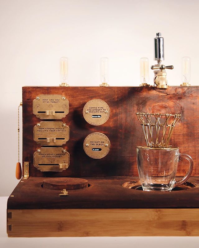
The interaction begins with the user selecting their answers to three questions about their current state and coffee preferences:

  1. How are you doing today? The response options are three emojis: great, meh, or tired. The user’s selection will correspond to the baseline amount of coffee needed. Someone doing great will be given more grams of coffee versus someone who is not.

  2. How strong would you like your coffee? Response options: Subtle, balanced, or bold. Selecting “subtle” lowers the number of grams whereas “bold” increases it.

  3. Which roast profile do you prefer? Response options: light, medium, or dark. The user’s preferred roast profile is matched to a specific bag of beans.

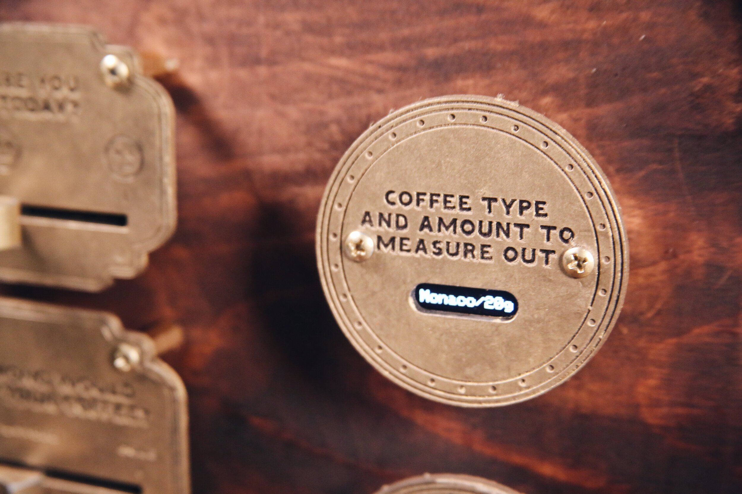
Based on the values of the user's selections, the machine would display which coffee beans to use and how many grams of coffee to measure for a perfect cup (in a 10 oz. mug), which were calculated according to coffee to water ratios ranging from 1:14 to 1:17.  For the class presentation, the coffee bean options were three roasts from La Colombe: Mexico, a light roast; Haiti, a medium roast; and Monaco, a dark roast.

After the machine displays the user's coffee type and number of grams, they scoop out the grounds until the weight on the scale matches the recommended amount. From there, they pour water into the bucket, place their coffee grounds into a paper filter sitting inside the brass filter basket, pull the lever down – and voilà! The steampunk coffee machine begins to heat the water and drip it right above the filter, preparing a cup of coffee for the user's enjoyment.

System Diagram

A diagram of the various components of the machine and how they were all connected together.

Code

The code for the scale and the potentiometers can be viewed at github.com/afaelnar/steampunk_coffee_machine.

Photos

Steampunk+Coffee+Machine+1.jpg

Midterm Project: Song of Swords

Concept

For the midterm project, the goal was to create a simple interactive system with physical controls. I partnered with Sammy Sords, who also works as stage combatant and teaches stage fighting with broadswords. We pursued the idea of pairing a broadsword with the Arduino and a speaker to teach sword fight parry positions and pacing. The tone would change upon the orientation or clash of the sword, and altogether, the movements would generate a song.

Process

We made use of the Arduino Nano 33 IoT’s built-in LSM6DS3 inertial motion unit (IMU), which is a 3-axis accelerometer and 3-axis gyroscope. We installed the Arduino LSM6DS3 library to read the values for acceleration and rotation and the Madgwick library to further determine the heading, pitch, and roll for the parry positions.

The code was based on the example provided for Determining Orientation. Sammy mounted the Arduino onto the sword and defined the orientation for four different parry positions (1st, 2nd, 3rd, and 4th) based on the serial monitor readings, and then we assigned a tone frequency to each position.

While we planned to also generate sound when the sword clashed with another sword, we weren’t able to resolve the issue of the gyroscope bouncing on impact, and so it was not part of the final result.

#include <Arduino_LSM6DS3.h>
#include <MadgwickAHRS.h>
 
// initialize a Madgwick filter:
Madgwick filter;
// sensor's sample rate is fixed at 104 Hz:
const float sensorRate = 104.00;
 
void setup() {
  Serial.begin(9600);
  // attempt to start the IMU:
  if (!IMU.begin()) {
    Serial.println("Failed to initialize IMU");
    // stop here if you can't access the IMU:
    while (true);
  }
  // start the filter to run at the sample rate:
  filter.begin(sensorRate);
}
 
void loop() {
  // values for acceleration & rotation:
  float xAcc, yAcc, zAcc;
  float xGyro, yGyro, zGyro;
   
  // values for orientation:
  float roll, pitch, heading;
  // check if the IMU is ready to read:
  if (IMU.accelerationAvailable() &&
      IMU.gyroscopeAvailable()) {
    // read accelerometer & gyrometer:
    IMU.readAcceleration(xAcc, yAcc, zAcc);
    IMU.readGyroscope(xGyro, yGyro, zGyro);
     
    // update the filter, which computes orientation:
    filter.updateIMU(xGyro, yGyro, zGyro, xAcc, yAcc, zAcc);
 
    // print the heading, pitch and roll
    roll = filter.getRoll();
    pitch = filter.getPitch();
    heading = filter.getYaw();
    Serial.print("Orientation: ");
    Serial.print(heading);
    Serial.print(" ");
    Serial.print(pitch);
    Serial.print(" ");
    Serial.println(roll);

      // play tone for parry position -- 1st
      if (xGyro > 80 && pitch <= 2 && roll >= 5) {
      tone(8, 523.25, 1000);
          delay(100);}

      // play tone for parry position -- 2nd
      else if (xGyro > 80 && pitch <=2 && roll < 5) {
      tone(8, 587.33, 1000);
          delay(100);}

      // play tone for parry position -- 3rd
      else if (xGyro > 80 && pitch > 2 && roll >= -5) {
      tone(8, 659.25, 1000);
          delay(100);}
          
      // play tone for parry position -- 4th
      else if (xGyro > 80 &&pitch > 2 && roll < -5) {
      tone(8,698.46,1000);
          delay(100);}
      }
}

Result

Sammy demonstrating the parry positions and the change in tone output with each position.

For the demonstration, Sammy attached the speaker to the glove of hand bearing the sword and powered the Arduino with a portable USB charger. The volume of the speaker ended up being too quiet during the in-class demo (which could be addressed in the future), but the tone output can be heard in the video above and fulfills our goal of providing sound feedback to the user.

Labs: Servo Motor Control and Tone Output

Following up our week four class, I revisited the tone output lab to practice using Arduino functions with the speaker. I wasn’t able to get my speaker to function last week (not sure if it was my circuit or my code), and I am still trying to get a grasp of the programming and how tones are generated.

The first step for me was soldering wires onto the speaker to make it easier to connect to the breadboard. The soldering tutorial in class was helpful as I felt much more confident with using the iron this time around (certainly noticed an improvement in technique since the first attempts to solder wires a couple of weeks ago for the switch lab).

The solder station set-up: a soldering iron, a fume extractor, brass wool for cleaning the solder tip, and helping hands holding up the speaker.

The solder station set-up: a soldering iron, a fume extractor, brass wool for cleaning the solder tip, and helping hands holding up the speaker.

After I got my speaker up and running, I wanted to more specifically test out tone melody output. I discovered that programming is currently my weakness.

I had encountered the codes for generating the notes of some recognizable songs, so I first attempted setting up three pushbuttons to each play a different song snippet. While each pushbutton did play a different melody as assigned, I had a couple of issues. First, the song would be cut short (only several notes would play), and second, I would have to re-upload the program again each time I wanted a button to play.

In my second attempt, I had two pushbuttons set up to play two Super Mario Bros. theme songs. The pushbuttons were playing the correct melody at first, and this time, the songs played in full and the pushbuttons worked continuously. However, I wanted to be able to switch between the two melodies depending on the button, but I couldn’t make it work.

In both cases, I’m wondering what I’m fundamentally missing with the code.

Two pushbuttons intended to play two different Super Mario Bros. theme songs with the Arduino: 1) the original melody, and 2) the underworld melody. The buttons play the assigned melody when initially pressed, but they don’t actually function to switch between the songs. Holding either of the pushbuttons down will continue playing the current song finish before going into the other song.

Observation and Labs: Arduino Digital and Analog

Labs

This past week, we focused on learning how to create circuits and write code for digital input/output and analog input with a microcontroller.

Lab two reviewed adding digital input (a pushbutton), adding digital outputs (LEDs), setting up the Arduino IDE, and programming the Arduino to set the inputs and outputs. Lab three demonstrated connecting analog input (a force-sensing resistor and a potentiometer), and utilizing the serial monitor to detect the range and state of the sensor (such as the level of force applied to the sensor).

While the labs enabled me to get a basic understanding of the digital input/output and analog input pins on the Arduino, I found the programming component more challenging, especially writing the code from scratch. I experimented with making minor tweaks to the code of the programs in the labs, such as making the LEDs blink with the push button, or changing the blinking speed of the LED.

I didn't feel confident enough yet to write my own code for the creative exercises, but one thing I wanted to learn was how to make one single pushbutton control two LEDs. I encountered a thread on the Arduino forum that discussed how one might be able to do this and tried out the code myself with the same circuit created in lab two.

The first press of the push button turned the red LED on, the second press turned the red LED off and the blue LED on, the third press turned both LEDs on, and the fourth press turned both LEDs off.

One push button programmed to control two LEDs.

Observation

In addition to completing the labs, we were asked to observe a piece of interactive technology in public that is used by multiple people. I observed the self-checkout machines for making purchases at a CVS pharmacy store.

My assumption for its use is that the machines provide shoppers with an expedited process: they give the shopper the ability to avoid the (sometimes long) line for the cashier and pay for and bag their purchases. The store can have multiple machines available for use and would only need someone to monitor them and troubleshoot any issues that arise with the machine or checkout process. By employing one cashier and one person to oversee the express checkout, the store would also not have to fully staff all of the registers.

When I entered the store, I counted four self-checkout machines, and two were in use. I noticed that other customers who came in at the same time quickly picked up a few items and then immediately went to the express checkout area. The machines have a clear purpose to customers: people knew what to do and were in and out of the store in only a couple of minutes.

One noticeable aspect of the self-checkout machines is the robotic voice that instructs the shopper through the process, which is audible even while in other parts of the store. As a person approaches, the machine senses their presence and says, "Welcome, please select your language. To start, simply begin scanning your items and follow the system prompts." There are two screens: 1) a large touchscreen that displays the scanned items and a selection of buttons for inputting a CVS ExtraCare Card number, choosing a form of payment, and scanning a coupon; 2) a credit card terminal that also provides a separate set of card-specific instructions for the transaction on a smaller screen.

I have personally used the express checkout enough times to get through the process without having to wait for the voice instructions, and know that there is a necessary step of selecting the payment type on the main touchscreen to process a credit card inserted in the terminal. (Before I knew this, I have stood at the machine waiting and not understanding why my payment wasn't being processed.) However, with the multiple screens, buttons, and instructions, some customers are not so familiar with the system and take more time to listen for guidance.

I also observed that the machines do not always operate so perfectly that a shopper would not need to request assistance from an employee. At one point, the voice from a machine says, "You have activated our inventory control system. Please see a cashier to complete your transaction." If a coupon deposited into a slot does not register as received, or the weight of an item that was meant to be placed in a bag is not detected, the machine indicates there is an issue with the transaction.

Observing these express checkout devices is a reminder of the limitations of machines and the importance of thoughtful design in addressing the frustrations that arise from such flaws. In The Psychopathology of Everyday Things, Don Norman wrote, "Machines usually follow rather simple, rigid rules of behavior. If we get the rules wrong even slightly, the machine does what it is told, no matter how insensible and illogical." However, Norman also noted, "Designers need to focus their attention on the cases where things go wrong, not just on when things work as planned. Actually, this is where the most satisfaction can arise: when something goes wrong but the machine highlights the problems, then the person understands the issue, takes the proper actions, and the problem is solved. When this happens smoothly, the collaboration of person and device feels wonderful."

In the case of the CVS self-checkout machine, there is a collaboration between the device and the user. It is not a perfect express checkout system on its own, but there is an ability for a user to make corrections. During my observation, the machine experiencing an issue alerted the customer, "Please wait. Help is on the way." The employee standing nearby moves over, taps a few buttons on the screen, and scans a white plastic card in their hand. The issue is resolved, and the customer moves on with satisfaction.

Lab: Electronics and Switches

In week two, we reviewed the basics of electronic circuits and components, and for the first time at ITP, we were given a physical computing kit that included most of the parts needed to complete the class labs.

The various components of the physical computing kit we received in class in order to start prototyping our own electrical circuits. Some of the basic components used for this week’s lab included the solderless breadboard, LEDs, resistors, solid cor…

The various components of the physical computing kit we received in class in order to start prototyping our own electrical circuits. Some of the basic components used for this week’s lab included the solderless breadboard, LEDs, resistors, solid core hookup wires, and the Arduino Nano 33 IoT.

The electronics labs for the week had us practice using a multimeter, building circuits, adding switches, and soldering connections — and after running through these exercises, we were asked to get creative with making our own switch.

I wanted to experiment with making a puzzle switch, and ended up going with the concept of assembling a pizza to complete a circuit. The idea was to have the pepperoni toppings function as switches by placing the felt pieces (with conductive foil underneath) on top of the wires that were embedded in the felt layer of cheese.

However, after I added in all of the wires, I found out that just placing the five pepperoni switches on top of the pizza did not provide a stable connection for the LED to light up. Because the felt circles are so lightweight, I had to press down firmly on all five pieces in order for the circuit to work. (If I were to make adjustments, I would consider the possibilities of other conductive materials and wiring methods.) I ended up simplifying the design to a single switch, so that laying down a final loose piece of pepperoni closed the circuit instead.

The final touch: placing the last pepperoni lights up the LED.

The final touch: placing the last pepperoni lights up the LED.